100% Pass Cisco, PMP, CISA, CISM, AWS Dumps on SALE!
Get Now
01:59:56
X
Optical modules and optical interfaces commonly used in switches
The optical modules commonly used in Ethernet switches are SFP, GBIC, XFP, XENPAK.
SFP: Small Form-factor Pluggabletransceiver
GBIC: GigaBit Interface Converter
XFP: 10-Gigabit small Form-factorPluggable transceiver
XENPAK: 10 Gigabit EtherNet TransceiverPAcKage
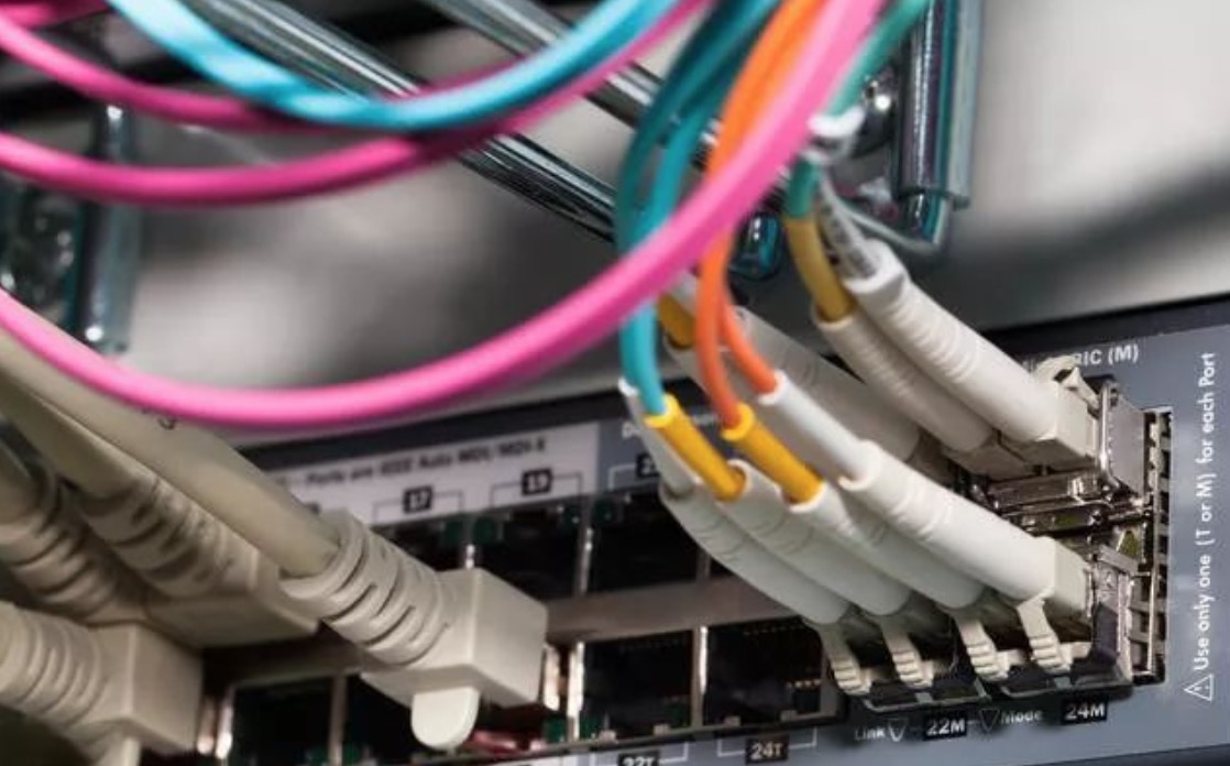
The optical fiber connector
The optical fiber connector is composed of optical fibers and plugs at both ends of the optical fiber. The plugs are composed of pins and peripheral locking structures. According to different locking mechanisms, optical fiber connectors can be divided into FC type, SC type, LC type, ST type and KTRJ type.
The FC connector adopts a threaded locking mechanism, which is an optical fiber movable connector that was invented earlier and used the most.
SC is a rectangular joint, developed by NTT, without screw connection, can be directly inserted and removed, compared with FC connector, it has a small operating space and is easy to use. Low-end Ethernet products are very common.
LC is a Mini-type SC connector developed by LUCENT. It has a smaller size and has been widely used in the system. It is a direction for the development of optical fiber active connectors in the future. Low-end Ethernet products are very common.
The ST connector was developed by AT&T, using a bayonet locking mechanism. The main parameters are equivalent to FC and SC connectors, but it is not commonly used in the company. It is usually used to connect multi-mode devices and connect with other manufacturers' equipment. Used more when docking.
The pins of KTRJ are made of plastic and are positioned by steel pins. With the increase of the number of insertions and withdrawals, the mating surfaces will wear out, and the long-term stability is not as good as ceramic pin connectors.
Fiber knowledge
Optical fiber is a conductor that transmits light waves. Optical fiber can be divided into single mode fiber and multimode fiber according to the mode of optical transmission.
There is only one fundamental mode for light transmission in single-mode fiber, which means that light is only transmitted along the inner core of the fiber. Because the mode dispersion is completely avoided, the transmission band of the single-mode optical fiber is very wide, so it is suitable for high-speed, long-distance optical fiber communication.
There are multiple modes of optical transmission in multimode fiber. Due to dispersion or aberration, the transmission performance of this fiber is poor, the frequency band is narrow, the transmission rate is small, and the distance is short.
Optical fiber characteristic parameters
The structure of the optical fiber is drawn from a prefabricated quartz optical fiber rod, and the outer diameter of the multi-mode optical fiber and single-mode optical fiber for communication is 125 μm.
Slimming is divided into two areas: Core and Cladding layer. The single-mode fiber core diameter is 8~10μm, and the multimode fiber core diameter has two standard specifications, the core diameter is 62.5μm (American standard) and 50μm (European standard).
The interface fiber specifications are described as follows: 62.5μm/125μm multimode fiber, where 62.5μm refers to the core diameter of the fiber and 125μm refers to the outer diameter of the fiber.
The wavelength of light used by single-mode fiber is 1310 nm or 1550 nm.
The wavelength of light used in multimode fiber is mostly 850 nm.
Single-mode fiber and multi-mode fiber can be distinguished by color. The outer body of single-mode fiber is yellow, and the outer body of multimode fiber is orange-red.
Gigabit optical port auto-negotiation
Gigabit optical ports can work in two modes: forced and auto-negotiation. The Gigabit optical port in the 802.3 specification only supports 1000M rate, and supports Full and Half modes.
The most fundamental difference between auto-negotiation and enforcement is that the two send different code streams when establishing a physical link. The auto-negotiation mode sends the /C/ code, which is the configuration code stream, and the forced mode sends the /I/ code. , Which is the idle code stream.
Gigabit optical port auto-negotiation process:
1. Both ends are set to auto-negotiation mode
The two parties send each other a /C/ code stream. If three consecutive /C/ codes are received in succession and the received code stream matches the local working mode, then a /C/ code with an Ack response is returned to the other party. After receiving the Ack message, the peer considers that the two can communicate with each other, and sets the port to the UP state
2. One end is set to auto-negotiation, one end is set to mandatory
The auto-negotiation terminal sends the /C/ code stream, and the compulsory terminal sends the /I/ code stream. The forced terminal cannot provide the peer with the local negotiation information, nor can it return an Ack response to the peer. However, the compulsory terminal itself can recognize the /C/ code and think that the opposite terminal is a port that matches itself, so directly set the local port to the UP state
3. Both ends are set to forced mode
Both sides send /I/ code stream to each other. After one end receives the /I/ code stream, it thinks that the opposite end is the port that matches itself, and directly sets the local port to the UP state
How does fiber work?
The optical fiber for communication is composed of hair-like glass filament covered with a plastic protective layer. The glass filament is essentially composed of two parts: a core with a diameter of 9 to 62.5 μm and a low refractive index glass material with a diameter of 125 μm.
Although there are some other types of optical fibers according to the materials used and different sizes, the most common ones are mentioned here. Light is transmitted in the "total internal reflection" mode of the core layer of the fiber, which means that after the light enters one end of the fiber, it is reflected back and forth between the core and the cladding interface, and then transmitted to the other end of the fiber. An optical fiber with a core diameter of 62.5 μm and a cladding outer diameter of 125 μm is called 62.5/125 μm light
What is the difference between multimode and singlemode fiber?
Multimode:
Fibers that can propagate hundreds to thousands of modes are called multimode fibers. According to the radial distribution of refractive index in the core and cladding, it can be divided into step multimode fiber and graded multimode fiber. Almost all multimode fiber sizes are 50/125μm or 62.5/125μm, and the bandwidth (the amount of information transmitted by the fiber) is usually 200MHz to 2GHz. Multimode optical transceiver can transmit up to 5 kilometers through multimode fiber. Use light-emitting diodes or lasers as the light source.
Single mode:
Fibers that can only propagate one mode are called single-mode fibers. The refractive index distribution of a standard single-mode fiber is similar to a step-type fiber, except that the core diameter is much smaller than that of a multimode fiber.
The size of single-mode fiber is 9-10/125μm, and it has the characteristics of unlimited bandwidth and lower loss than multimode fiber. Single-mode optical transceivers are mostly used for long-distance transmission, sometimes reaching 150 to 200 kilometers. Use LD or LED with narrow spectral line as light source.
Differences and connections:
Single-mode devices can usually run on single-mode fiber or multi-mode fiber, while multi-mode devices are limited to multi-mode fiber.
What is the transmission loss when using optical cables?
This depends on the wavelength of the transmitted light and the type of optical fiber used.
When 850nm wavelength is used for multimode fiber: 3.0dB/km
1310nm wavelength for multimode fiber: 1.0 dB/km
1310nm wavelength for single-mode fiber: 0.4 dB/km
1550nm wavelength for single mode fiber: 0.2dB/km
What is GBIC?
GBIC is the abbreviation of Giga Bitrate Interface Converter, which is an interface device that converts gigabit electrical signals into optical signals. GBIC is designed for hot swapping. GBIC is an interchangeable product that meets international standards. Gigabit switches designed with the GBIC interface occupy a large market share in the market due to their flexible interchangeability.
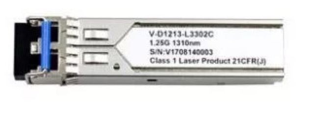
What is SFP?
SFP is the abbreviation of SMALL FORM PLUGGABLE, which can be simply understood as an upgraded version of GBIC. The SFP module volume is reduced by half compared to the GBIC module, and more than double the number of ports can be configured on the same panel. The other functions of the SFP module are basically the same as GBIC. Some switch manufacturers call SFP modules miniaturized GBIC (MINI-GBIC).
In the future, the optical module must support hot plugging, that is, the module can be connected or disconnected from the device without cutting off the power supply. Because the optical module is hot pluggable, the network administrator can upgrade and expand the system without shutting down the network. The user will not cause any impact. Hot swappability also simplifies the overall maintenance work and enables end users to better manage their transceiver modules.
At the same time, due to this hot-swappable performance, this module enables network managers to plan overall cost of transmission and reception, link distance, and all network topologies based on network upgrade requirements, without having to replace all system boards. The optical modules that support this hot swap are currently GBIC and SFP. Due to the similar size of SFP and SFF, it can be directly inserted on the circuit board, which saves space and time on the package, and has a wide range of applications. Therefore, Its future development is worth looking forward to, and may even threaten the SFF market.
What is SFF?
SFF (Small Form Factor) small package optical module adopts advanced precision optics and circuit integration technology, the size is only half of the ordinary duplex SC (1X9) type optical fiber transceiver module, and the number of optical ports can be doubled in the same space. Increase the line port density and reduce the system cost per port. And because the SFF small package module uses a KT-RJ interface similar to the copper wire network, the size is the same as the common computer network copper wire interface, which is conducive to the transition of the existing copper-based network equipment to a higher-speed optical fiber network To meet the rapid growth of network bandwidth requirements.
Network connection device interface type
BNC interface
The BNC interface refers to the coaxial cable interface. The BNC interface is used for 75-ohm coaxial cable connection. It provides two channels for receiving (RX) and transmitting (TX). It is used for the connection of unbalanced signals.
Fiber optic interface
Optical fiber interface is a physical interface used to connect optical fiber cables. There are usually several types such as SC, ST, LC, and FC. For the 10Base-F connection, the connector is usually ST type, and the other end of the FC is connected to the optical fiber walking frame. FC is the abbreviation of FerruleConnector, the external reinforcement method is to use metal sleeve, and the fastening method is screw buckle. The ST interface is usually used for 10Base-F, the SC interface is usually used for 100Base-FX and GBIC, and the LC interface is usually used for SFP.
RJ-45 interface
The RJ-45 interface is the most commonly used interface for Ethernet. RJ-45 is a commonly used name, referring to the standardization by IEC (60) 603-7, using 8 positions (8 pins) defined by the international connector standard Modular jack or plug.
RS-232 interface
RS-232-C interface (also known as EIA RS-232-C) is currently the most commonly used serial communication interface. It is a standard for serial communication jointly developed by the American Electronics Industry Association (EIA) in conjunction with Bell Systems, modem manufacturers, and computer terminal manufacturers in 1970. Its full name is "Technical Standard for Serial Binary Data Exchange Interface between Data Terminal Equipment (DTE) and Data Communication Equipment (DCE)". The standard specifies the use of a 25-pin DB25 connector to specify the signal content of each pin of the connector, as well as the level of various signals.
RJ-11 interface
The RJ-11 interface is what we usually call the telephone line interface. RJ-11 is a common name for connectors developed by Western Electric. Its shape is defined as a 6-pin connecting device. Formerly known as WExW, x here means "active", contact or needle. For example, WE6W has all 6 contacts, numbered 1 to 6, WE4W interface uses only 4 pins, the outermost two contacts (1 and 6) do not, WE2W only uses the middle two pins (that is, telephone line interface).
CWDM and DWDM
With the rapid growth of Internet's IP data services, the demand for transmission line bandwidth is increasing. Although DWDM (Dense Wavelength Division Multiplexing) technology is the most effective method to solve the problem of line bandwidth expansion, CWDM (Coarse Wavelength Division Multiplexing) technology has advantages over DWDM in terms of system cost and maintainability.
Both CWDM and DWDM belong to wavelength division multiplexing technology, and can couple light of different wavelengths into single-core optical fibers and transmit them together.
CWDM's latest ITU standard is G.695, which stipulates 18 wavelength channels with an interval of 20nm from 1271nm to 1611nm. Considering the water peak effect of ordinary G.652 fiber, 16 channels are generally used. Because the channel spacing is large, the combined and demultiplexed devices and lasers are cheaper than DWDM devices.
The channel spacing of DWDM has different spacings such as 0.4nm, 0.8nm, 1.6nm, etc. The spacing is smaller and additional wavelength control devices are needed, so equipment based on DWDM technology is more expensive than equipment based on CWDM technology.
PIN photodiode is a layer of lightly doped N-type material, called I (Intrinsic, intrinsic) layer, between P-type and N-type semiconductors with high doping concentration. Because it is lightly doped, the electron concentration is very low, and a wide depletion layer is formed after diffusion, which can improve its response speed and conversion efficiency.
APD avalanche photodiode, not only has a light/electric conversion effect, but also has an internal amplification effect, which is achieved by the avalanche multiplication effect inside the tube.
APD is a photodiode with gain. In situations where the sensitivity of the optical receiver is high, the use of APD is beneficial to extend the transmission distance of the system.
The above is the news sharing from the PASSHOT. I hope it can be inspired you. If you think today' s content is not too bad, you are welcome to share it with other friends. There are more latest Linux dumps, CCNA 200-301 dumps, CCNP Written dumps and CCIE Written dumps waiting for you.
Related Dumps


Cisco Dumps Popular Search:
spoto china patterns cisco ccna exam are you ready 350-801 clcor book pdf ccna pdf notes with practical spoto ccie r& cisco ccna lab cisco ccna exam fees best ccnp tshoot book 200 301 training 200-301-a88
User Links
Latest Dumps

Copyright © 2026 PASSHOT All rights reserved.